Wheels and axles in modern driveline systems for load, torque and fitment

Understanding wheels and axles as one driveline interface
Wheels and axles are more than two parts joined near the tire. In a modern driveline system, they form a wheel-end interface where vehicle weight, drive torque, braking force, steering geometry, bearing support and fastening loads all converge. The wheel provides the mounting and tire support surface. The axle may transmit torque, carry vertical load, locate the wheel end, or combine these functions depending on the vehicle layout. For that reason, wheel size, axle type, hub pattern, load rating and bearing arrangement should not be reviewed in isolation.
For parts buyers, technicians and engineering teams, the practical question is not only whether a wheel will bolt onto an axle. The more useful question is whether the complete wheel-end package can handle the vehicle’s rated load, torque path, duty cycle, suspension movement, brake package and service environment. This article takes that system view across passenger cars, light trucks, commercial vehicles, hybrids and electric vehicles.
For broader category context, see the Driveline Systems section, which covers related drivetrain, axle and wheel-end topics.
What each part actually does
The word wheel is often used casually to describe the complete tire-and-wheel assembly. In technical parts work, however, it usually refers to the rim and disc or center structure that supports the tire and attaches to the hub. The tire carries the contact patch. The wheel supports the tire bead, provides the bolt or stud interface, and must resist radial, lateral and fatigue loads during operation.
The axle is a broader term. It may refer to a rotating axle shaft, a complete drive axle assembly, a non-driven beam axle, a trailer axle, a steer axle, or an integrated electric axle module. In a front-wheel-drive passenger car, the “front axle” in service language may mean the half-shafts and constant velocity joints. In a body-on-frame rear-drive truck, the rear axle may include the housing, differential, axle shafts, bearings, seals and wheel-end mounting points.
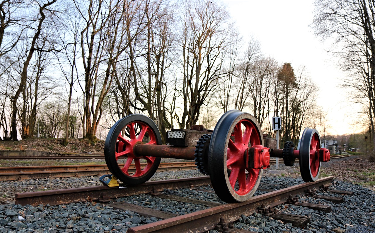
The hub sits between these two concepts. It usually carries the wheel fasteners and rotates on bearings. In many vehicles, the wheel bolts to the hub, the hub is supported by a bearing, and the axle shaft transmits torque through the hub by splines or a flange. This separation matters in diagnosis because vibration, noise or looseness can originate from the tire, wheel, hub, bearing, axle shaft, differential, brake rotor or suspension joint.
The wheel-to-axle load path
Every wheel-end design has a defined load path. Vertical load travels from the vehicle through the suspension, axle structure, bearings, hub, wheel and tire to the road. Drive torque travels from the engine, transmission, motor or reduction gear through shafts and splines toward the wheel. Braking torque is managed in the opposite functional direction as the tire contact patch resists rotation and loads pass through the wheel, hub, bearings, axle mounting and suspension structure.
This is why a wheel that physically fits may still be a poor match. Offset changes the leverage applied to bearings and suspension joints. Wheel diameter can affect brake clearance and available tire load choices. Center bore or centering errors can create runout or vibration. Incorrect fastener seat shape, thread engagement or torque can reduce clamping force. The axle and wheel have to be evaluated together because the interface carries repeated cyclic loads, not just a single static catalog load.
Industry standards reinforce this system approach. ISO 3911:2021 covers vocabulary, designation and marking for wheels and rims for pneumatic tyres. SAE J328 addresses performance requirements and test procedures for passenger car and light truck wheels. SAE J393 provides nomenclature for commercial vehicle wheels, hubs and rims. In the United States, FMVSS No. 110 and FMVSS No. 120 address tire selection, rims and load-carrying information for different vehicle weight classes. These references do not replace vehicle-specific service data, but they show that terminology, marking, load and fitment details are treated as safety-relevant information.
How driveline layout changes the axle role
A front-wheel-drive vehicle usually combines the transmission and final drive into a transaxle. Short half-shafts deliver torque to the front wheels through CV joints while accommodating steering angle and suspension travel. In this layout, wheel and axle decisions are closely tied to joint angles, shaft length, boot clearance, hub spline specification and bearing load.
A conventional rear-wheel-drive vehicle separates the engine, transmission, driveshaft, differential and rear axle. The rear axle may be a solid axle assembly or an independent rear suspension with half-shafts. A solid drive axle can be robust for towing and payload work, while independent layouts can improve ride and wheel control. Both designs still depend on correct wheel offset, hub fitment, bearing capacity and axle shaft strength.
All-wheel-drive and four-wheel-drive systems add another layer because torque can be sent to more than one axle. A transfer case, power transfer unit, electronically controlled coupling, rear drive module or second electric drive unit may change how loads appear at the wheel end. Tire rolling circumference also becomes more important because mismatched tire sizes can create driveline stress in some AWD systems.
Electric vehicles do not remove axle engineering. They change the package. The International Energy Agency’s Global EV Outlook 2026 reported that electric car sales exceeded 20 million globally in 2025, about one-quarter of new car sales. As electric drive units become more common, engineers still need shafts, bearings, gears, housings, seals, mounts and wheel-end interfaces. EV torque delivery can be very quick, regenerative braking changes load patterns, and reduced engine noise can make gear whine, bearing noise or wheel vibration more noticeable.
Fitment factors that should be checked together
A useful compatibility review connects wheel data, axle data and vehicle data. The table below organizes the checks that often determine whether a wheel-end package is suitable.
| Fitment area | What to verify | Why it matters |
|---|---|---|
| Wheel size and rim profile | Diameter, width, bead seat profile and tire approval | Supports correct tire mounting, brake clearance and load capacity |
| Bolt pattern and fasteners | PCD, stud or bolt size, seat type, thread engagement and torque procedure | Maintains clamping force and helps prevent movement at the hub face |
| Center bore and hub location | Hub-centric or lug-centric design, bore diameter and spacer use | Controls centering accuracy and helps reduce vibration risk |
| Offset and track change | Original offset range, scrub radius impact and bearing leverage | Affects steering feel, bearing load, fender clearance and suspension geometry |
| Axle and hub rating | GAWR, bearing capacity, hub design and wheel load rating | Prevents pairing a strong component with a weaker connected component |
| Brake and sensor clearance | Caliper envelope, rotor size, ABS wiring and tone ring position | Avoids interference and electronic fault issues after installation |
| Torque path | Spline count, shaft diameter, CV joint angle, differential ratio and motor or engine torque | Ensures the axle can transmit real operating loads, not only static weight |
Gross axle weight rating, or GAWR, is especially important for trucks, vans, trailers and towing applications. GAWR is assigned by the vehicle manufacturer for a specific axle position and reflects more than the axle beam or shaft alone. Tires, rims, hubs, bearings, brakes, suspension and vehicle configuration all influence the certified axle load. A wheel upgrade that ignores GAWR can create a mismatch even when the visual fit appears acceptable.
Service symptoms at the wheel and axle interface
Because the wheel-end system connects many parts, symptoms can be misleading. A clicking sound during turns is commonly associated with outer CV joint wear, but tire contact, brake hardware or loose shields can also create noise. A humming sound may come from a wheel bearing, tire pattern, differential bearing or gear mesh. Vibration under acceleration can point to an axle shaft, CV joint, driveshaft angle, wheel balance issue, mount movement or tire uniformity problem.
A structured inspection should start with visible safety items: tire condition, wheel damage, missing weights, loose or damaged fasteners, oil or grease leakage, cracked boots, brake interference and abnormal heat. The next step is to check runout, bearing play, axle shaft condition, hub face cleanliness and suspension joint movement. On vehicles with electronic stability control, ABS or electric drive modules, diagnostic trouble codes and sensor data can help separate mechanical faults from control or signal problems.
Parts replacement should also address the reason the component failed. A new CV shaft may fail early if an engine mount is collapsed and operating angles are excessive. A replacement wheel bearing may become noisy again if the wheel offset is far outside the intended range. A new wheel may vibrate if the hub face is corroded or the fasteners use the wrong seat profile. Wheel and axle service is therefore a process of confirming the connected system, not simply installing the component that looks damaged.
What electrification and heavier duty cycles change
Modern driveline design is moving in two directions at the same time. Passenger vehicles are adopting more integrated electric drive units, while pickups, vans and commercial vehicles are expected to handle higher payload, towing and delivery-cycle demands. Both trends increase the importance of wheel-end durability.
Electric drive can place high torque near the axle instead of sending it through a long mechanical path from a front engine. This gives engineers packaging flexibility, but it also concentrates mechanical, thermal and electronic requirements. Bearings, seals, gear lubrication, motor cooling, inverter placement and axle housing stiffness may need to be considered as one module. Regenerative braking also means some braking energy passes through the electric drive strategy, changing how torque is managed during deceleration.
Commercial and fleet applications create a different stress profile. Frequent starts, curb impacts, high payload variation, trailer loads, road salt, long service intervals and heat can all shorten component life. Wheel selection for these vehicles should consider duty cycle, not only appearance or nominal size. For an expanded explanation of axle functions inside the driveline, see How an axle works in a driveline system.
Practical checklist for parts and service decisions
Before ordering or approving wheel and axle-related parts, a short checklist can prevent many avoidable errors:
- Confirm the exact vehicle application, trim, model year, drive layout and axle position.
- Compare the wheel size, offset, bolt pattern, center bore and fastener seat with vehicle specifications.
- Check tire load rating and inflation requirements against the axle position and intended use.
- Verify axle shaft spline details, hub interface, bearing type and ABS or speed sensor arrangement.
- Inspect brake clearance, suspension travel and steering lock clearance before road use.
- Review service instructions for fastener torque, bearing preload, axle nut procedure and lubrication.
- Consider duty cycle, including towing, delivery work, off-road use, high load, corrosion exposure and EV torque response.
- After installation, road test for vibration, noise, braking feel, warning lights and abnormal heat at the wheel end.
The central lesson is straightforward: wheels and axles should be selected as a matched system. The strongest axle, largest wheel or most aggressive fitment is not automatically the best choice. Reliable driveline performance comes from matching wheel-end geometry, load rating, torque path, bearing support, brake package and service environment to the actual vehicle.
Frequently asked questions
Are wheels and axles the same thing?
No. The wheel supports the tire and attaches to the hub. The axle may support load, transmit torque, locate the wheel end or form part of a larger drive assembly. They work together, but they are different parts of the wheel-end system.
Can a wheel fit the bolt pattern but still be wrong?
Yes. Bolt pattern is only one fitment factor. Offset, center bore, load rating, fastener seat, brake clearance, tire compatibility and hub design also matter. A wheel can bolt on and still create bearing load, vibration or clearance problems.
Do EVs still need axles?
Yes. EVs may use integrated electric drive units instead of a traditional engine-to-driveshaft layout, but they still need axle shafts, bearings, hubs, gears, seals and wheel-end structures to carry load and deliver torque to the road.
Why does wheel offset affect axle and bearing life?
Offset changes where the tire contact load acts relative to the hub and bearing. Moving the wheel centerline too far inward or outward can increase leverage on bearings, suspension joints and steering geometry, especially under cornering or payload loads.
What is the safest first step when diagnosing wheel-end vibration?
Start with the basics: tire condition, wheel balance, wheel damage, fastener torque, hub face cleanliness and visible bearing or axle play. Then move into axle shaft, CV joint, driveshaft, suspension and electronic checks as needed.